Automating ACI Multi-site BGWs with Network as Code
Estimated time to read: 12 minutes
- Originally Written: May, 2026
Info
This post uses the Nexus as Code (NaC) project which makes it very easy to configure ACI fabrics through a YAML file . More details and examples can be found at https://netascode.cisco.com
Overview
If you're been working with ACI you might know that there are different architectures.
Single fabric, single site- single fabric, single APIC controller cluster (virtual or physical controllers)Multi-pod- multiple fabrics, single APIC controller clusterMulti-site- multiple fabrics, multiple APIC controller clusters
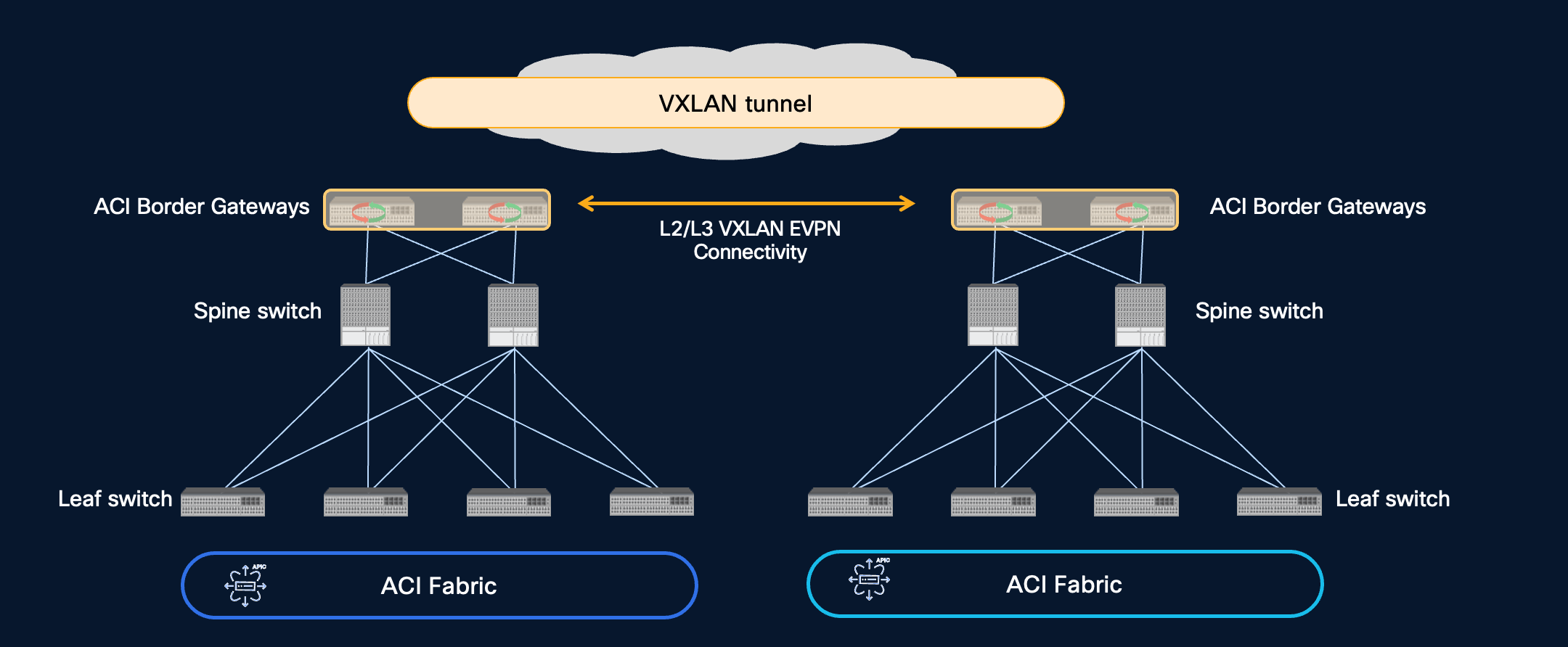
ACI Multi-site has always been configured with Nexus Dashboard Orchestrator (previous known as Multi-site Orchestrator or MSO) and allowed you to manage multiple ACI sites as well as stretch L2/L3 between the sites. It did this by creating MP-BGP EVPN session and VXLAN tunnels between the spine nodes deployed in separate fabrics. These sessions and tunnels were used provide host reachability to endpoints in each fabric for those that needed to communicate.
For more detail have a look at the ACI Multi-site Whitepaper
There is now a new way to configure ACI Multi-site and it uses the concept of a Border Gateway (BGW). This has been possible since APIC 6.1(1) release. The BGW concept has been available in VXLAN fabrics for some time and ACI follows the same concept. So now rather than building connectivity between the spines, you can connect the sites through the BGWs the same way you would for a standard VXLAN Multi-site deployment.
This makes the config really simple as you just need to configure one site, clone the config for the second site, and then update the specific local site values (including pointing Terraform at the site-02 APIC cluster).
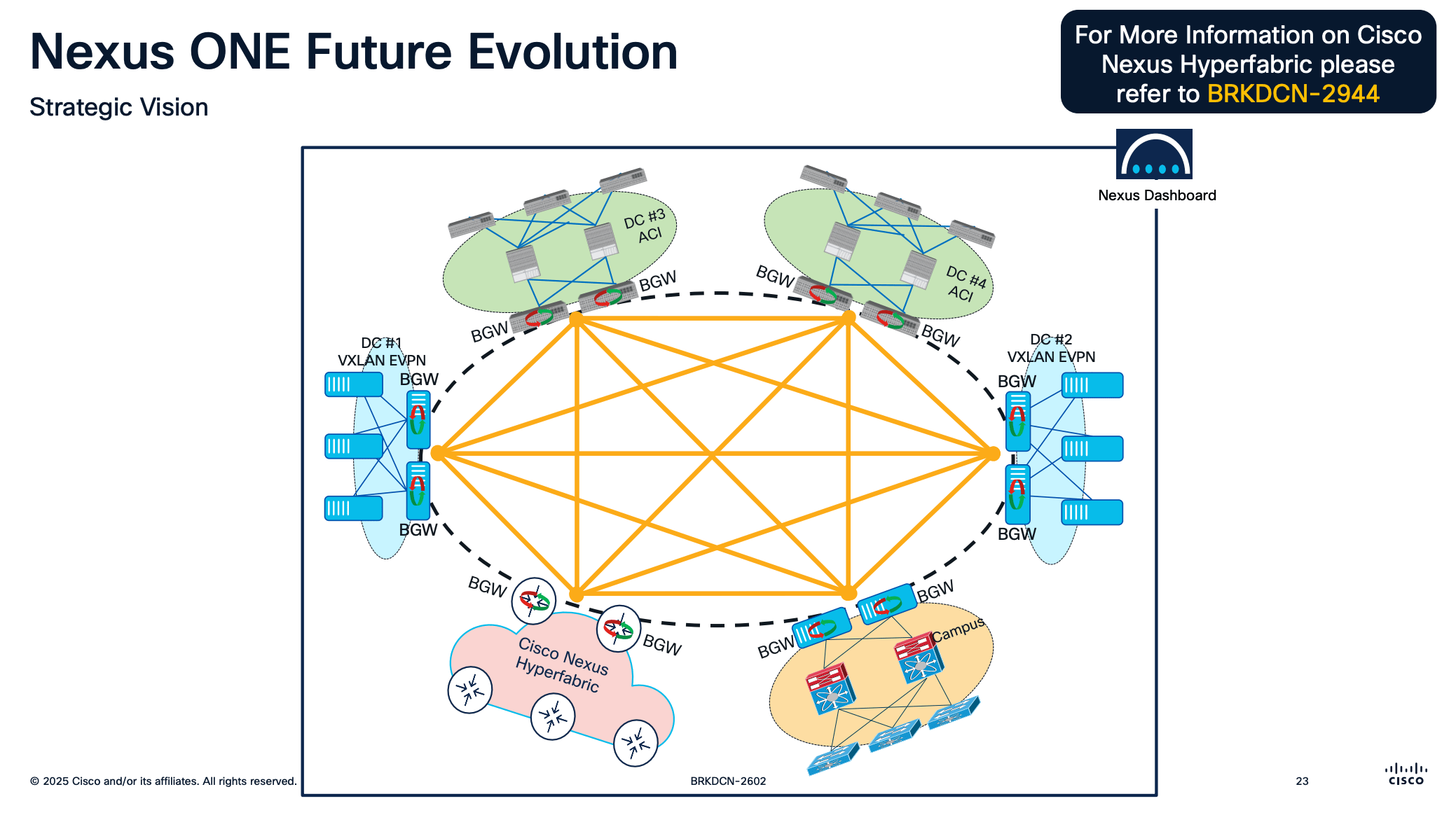
This is one component of the Nexus ONE architecture which is a marketing term for a set of capabilities in the Nexus portfolio to provide better interoperability between the various offerings.
Have a look at this Cisco Live presentation for more information. You can also find the session video in the On Demand Catalog at https://www.ciscolive.com.
Automating ACI Multi-site with Network as Code
This brings me to the point of this post which is how you can configure Multi-site with Network As Code. Since this post is focused on the automation I'm not going into the BGW specifics. The ACI BGW Configuration Guide has a lot more information on the configuration, guidelines, caveats etc
Demo Setup
Here is the demo setup so you understand the various addresses/interfaces found in the config below.
First a BGP session is setup from the ACI BGW to the Inter-site Network (the ISN is just a routed network. It could be your core switches configured with a separate VRF). This will provide reachability between a loopback configured on each BGW.
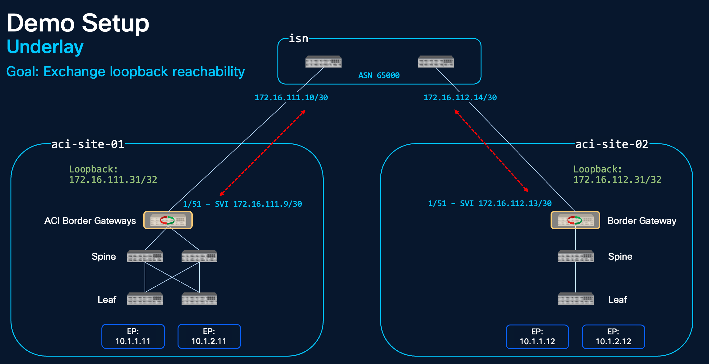
Once the loopbacks are reachable from each site a BGP EVPN session is setup between them. This session is used to exchange the endpoints and routes found in each site.
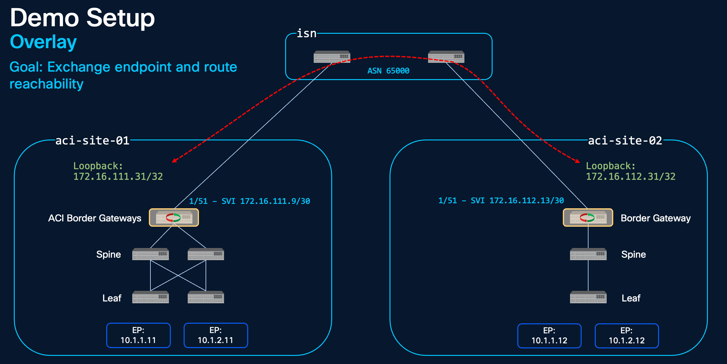
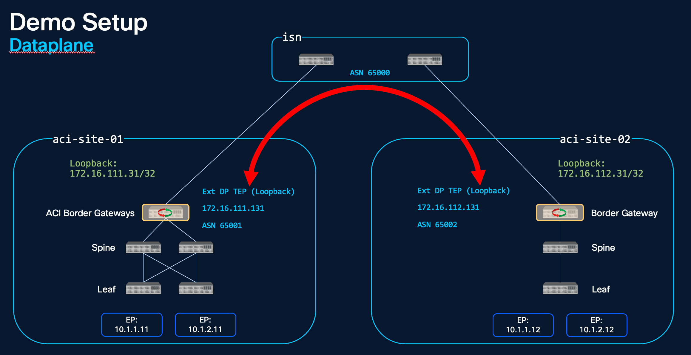
The final address/interface is the External Dataplane Tunnel Endpoint (another loopback) which is used as the outer source/destination address when traffic is sent from one endpoint to another across sites.
Configuration General Overview
As you'll see below the config is quite straight forward but there are a couple of points to highlight. At a high level you'll configure the following twice:
- BGW switches
- Site to site connection (VXLAN L3Out)
- Tenant objects (stretched VRF/BD/ESG)
The same objects are deployed in each site, just with different identifiers (e.g. Loopback IPs) so you clone site-01 config for site-02 and update the site specific config. You'll also need to update the URL/Credentials to deploy the site-02 config to the correct APIC.
Configuration: Border Gateway Role
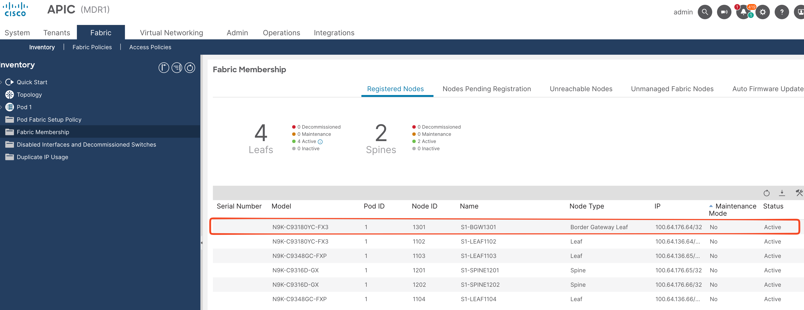
Please note that at the time of writing the BGW is a dedicated leaf role and at the time of writing there is no NaC support for this role. Please check the APIC release notes/BGW configuration guide as well as the NetAsCode documents to see if this is still the case when you're deploying it.
Just add the new switch as you would a standard ACI switch, select the BGW role, and then add the Node Name and Node ID.
Configuration: Terraform Module
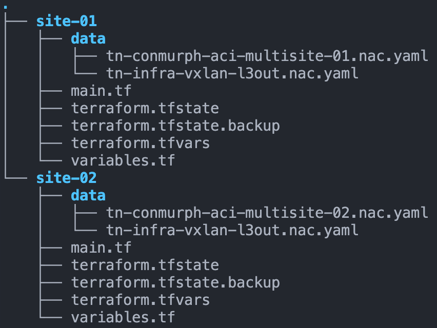
I've split up the config into two folders/repositories. Each folder represents a site and contains the main.tf file and the YAML data files for that site. The main.tf calls the ACI NaC modules and contains the APIC URL/credentials for that specific site.
terraform {
  required_providers {
    aci = {
      source  = "CiscoDevNet/aci"
      version = ">=2.18.0"
    }
  }
}

provider "aci" {
  username = var.apic_username
  password = var.apic_password
  url      = var.apic_url
}

module "aci" {
  source = "github.com/netascode/terraform-aci-nac-aci?ref=main"
  version = ">=1.2.0"


  yaml_directories = ["data"]

  manage_access_policies    = false
  manage_fabric_policies    = false
  manage_pod_policies       = false
  manage_node_policies      = false
  manage_interface_policies = false
  manage_tenants            = true
}
Configuration: Infra Tenant VXLAN L3out
There are two main components to configure, the infra tenant (VXLAN L3Out) and the user tenant (stretched VRF/BDs). I like to keep these in separate YAML files for readability. This is the infra tenant config and I've explained some of the objects in the comments.
aci-site-01-infra-tenant.yaml
---
# aci-site-01-infra-tenant
apic:
tenants:
    - name: infra
    managed: false

    vxlan_l3outs:
        - name: vxlan-l3out
        description: VXLAN L3Out used for ACI Multi-site
        border_gateway_set_policy: site-01-bgw-set-01

        node_profiles:
            - name: bgw-nodes
            description: The nodes registered with the BGW role
            nodes:
                - node_id: 1301
                pod_id: 1
                loopback: 172.16.111.31/32 # BGP session to second site loopback - used to share endpoint reachability
            interface_profiles:
                - name: bgw-interfaces
                description: The external interfaces which connect to the ISN
                interfaces:
                    - node_id: 1301
                    port: 51
                    mtu: 9216
                    ip: 172.16.111.9/30 # BGP session to ISN - used to provide reachability between site loopbacks
                    bgp_peers:
                        - ip: 172.16.111.10
                        description: core-01
                        remote_as: 65000
                        admin_state: true

    policies:
        border_gateway_set_policy:
        name: site-01-bgw-set-01
        vxlan_site_id: 100
        external_data_plane_ips:
            - pod_id: 1
            ip: 172.16.111.131 # used as out VXLAN source/destination when sending traffic between sites
        remote_vxlan_fabrics:
        - name: site-02
            border_gateway_set_policy: site-01-bgw-set-01
            remote_evpn_peers:
            - ip: 172.16.112.31 # The peer loopback address which is used in BGP session to the second site
                remote_as: 65002
                description: aci-site-02
                admin_state: true
aci-site-02-infra-tenant.yaml
---
# aci-site-01-infra-tenant.yaml
apic:
tenants:
    - name: infra
    managed: false

    vxlan_l3outs:
        - name: vxlan-l3out
        description: VXLAN L3Out used for ACI Multi-site
        border_gateway_set_policy: site-02-bgw-set-01

        node_profiles:
            - name: bgw-nodes
            description: The nodes registered with the BGW role
            nodes:
                - node_id: 2301
                pod_id: 1
                loopback: 172.16.112.31/32
            interface_profiles:
                - name: bgw-interfaces
                description: The external interfaces which connect to the ISN
                interfaces:
                    - node_id: 2301
                    port: 51
                    mtu: 9216
                    ip: 172.16.112.13/30
                    bgp_peers:
                        - ip: 172.16.112.14
                        description: core-01
                        remote_as: 65000
                        admin_state: true

    policies:
        border_gateway_set_policy:
        name: site-02-bgw-set-01
        vxlan_site_id: 200
        external_data_plane_ips:
            - pod_id: 1
            ip: 172.16.112.131
        remote_vxlan_fabrics:
        - name: site-02
            border_gateway_set_policy: site-02-bgw-set-01
            remote_evpn_peers:
            - ip: 172.16.111.31
                remote_as: 65001
                description: aci-site-02
                admin_state: true
Configuration: User Tenant Stretched VRFs and BDs
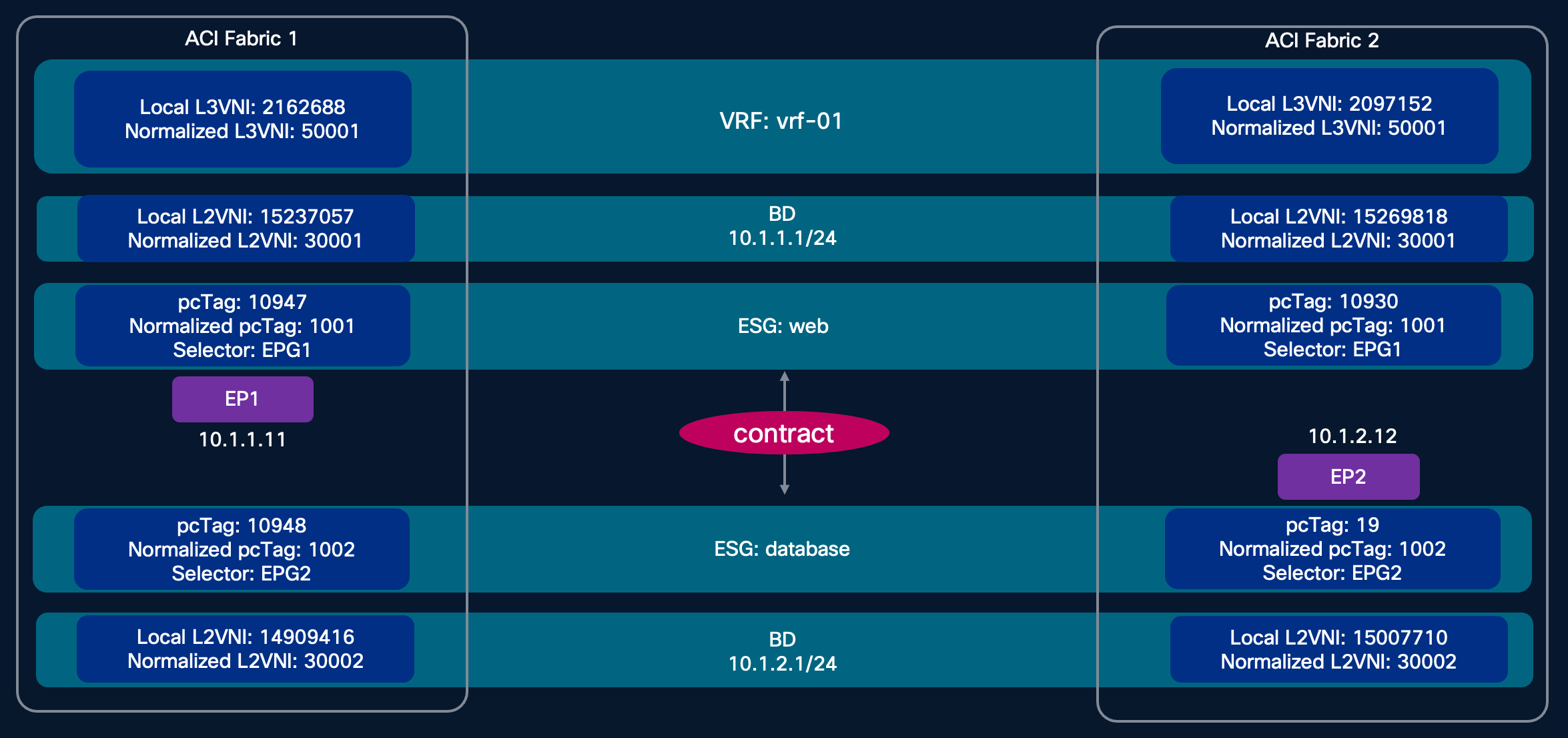
This is the configuration for the user tenant. For the demo I called it conmurph-aci-multisite-01 in site-01 and conmurph-aci-multisite-02 in site-02 but you could keep it the same in a production environment. Most of the config as you'll see is the same as you would find in any ACI fabric i.e. VRFs, BDs, EPGs, ESGs, Contracts. To stretch a VRF or BD you just add the vxlan_stretch: resource. You then reference the border_gateway_set_policy and the normalized_vni. Also note that the policy tag (pcTag) for the ESG is normalized so you can apply a consistent security policy (using contracts) across sites
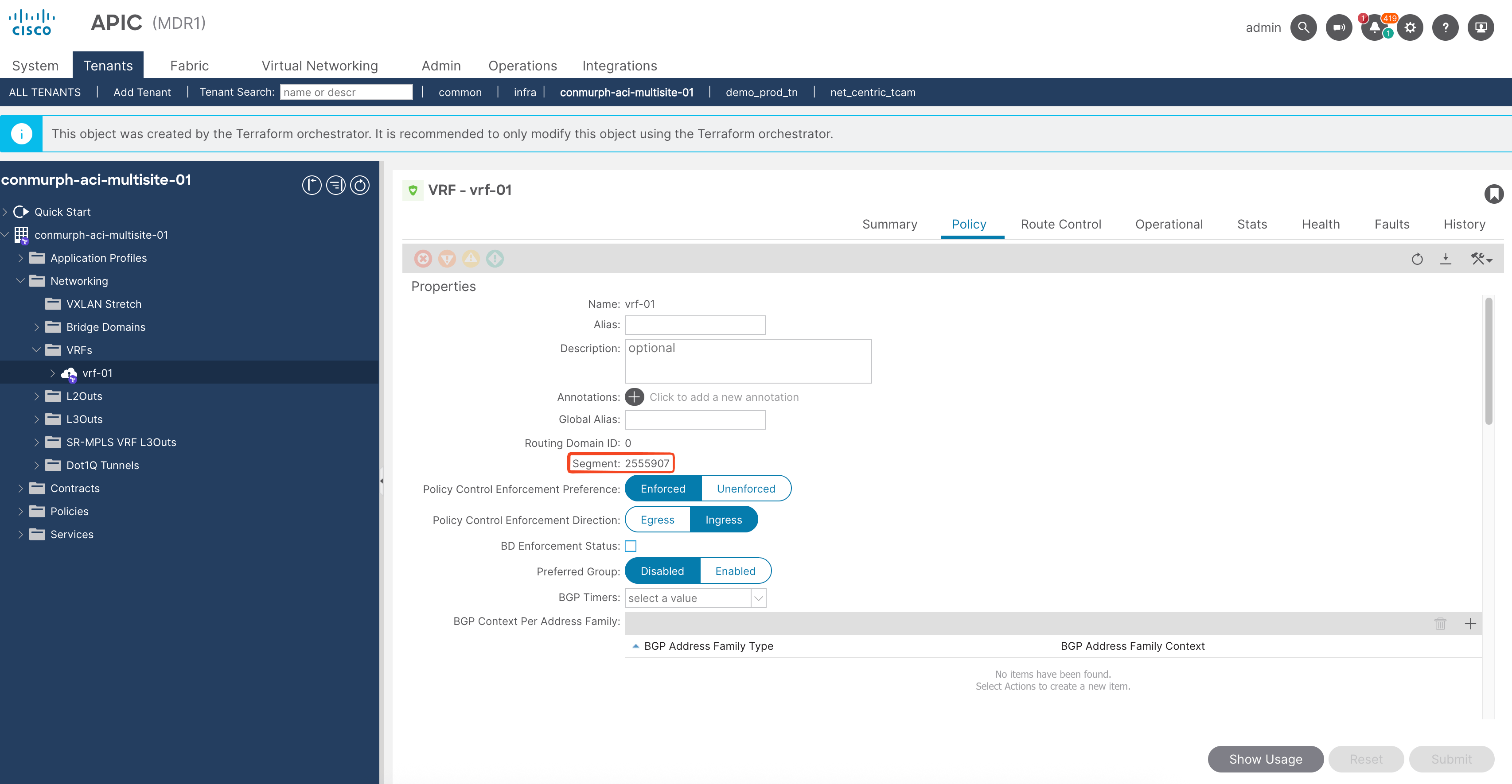
Normalized VNI
When you configure an ACI VRF or Bridge Domain there is no way to configure the L3/L2 VXLAN VNI, it is automatically selected for you. If you configure a VRF in two ACI sites you will most likely end up with a different VNI in each site. When you stretch a VRF/BD between sites you need a way to map the two respective VNIs. This is the role of the normalized VNI. i.e. aci-site-01-l3vni: 2162688 -> normalized_vni: 50001 <- aci-site-03-l3vni: 2097152
aci-site-01-user-tenant.yaml
---
# aci-site-01-user-tenant
apic:
tenants:
    - name: conmurph-aci-multisite-01
    managed: true

    vrfs:
        - name: vrf-01
        vxlan_stretch:
            border_gateway_set_policy: site-01-bgw-set-01
            normalized_vni: 50001

    bridge_domains:
        - name: 10.1.1.0_24
        vrf: vrf-01
        unknown_unicast: flood
        subnets:
            - ip: 10.1.1.1/24
            public: true
        vxlan_stretch:
            normalized_vni: 30001
            border_gateway_set_policy: site-01-bgw-set-01
        - name: 10.1.2.0_24
        vrf: vrf-01
        unknown_unicast: flood
        subnets:
            - ip: 10.1.2.1/24
            public: true
        vxlan_stretch:
            normalized_vni: 30002
            border_gateway_set_policy: site-01-bgw-set-01
        - name: 10.1.3.0_24
        vrf: vrf-01
        unknown_unicast: flood
        subnets:
            - ip: 10.1.3.1/24

    application_profiles:
        - name: network-segments
        managed: true

        endpoint_groups:
            - name: 10.1.1.0_24
            bridge_domain: 10.1.1.0_24
            vmware_vmm_domains:
                - name: vmm_vds
                deployment_immediacy: immediate
                resolution_immediacy: immediate
            - name: 10.1.2.0_24
            bridge_domain: 10.1.2.0_24
            vmware_vmm_domains:
                - name: vmm_vds
                deployment_immediacy: immediate
                resolution_immediacy: immediate

        - name: network-segments
        endpoint_security_groups:
            - name: 10.1.1.0_24
            vrf: vrf-01
            epg_selectors:
                - endpoint_group: 10.1.1.0_24
            normalized_pctag: 1001 # pcTag is normalized to provide consistent security policy across sites
            contracts:
                providers:
                - permit-to-10.1.1.0_24
            - name: 10.1.2.0_24
            vrf: vrf-01
            epg_selectors:
                - endpoint_group: 10.1.2.0_24
            normalized_pctag: 1002
            contracts:
                consumers:
                - permit-to-10.1.1.0_24

    filters:
        - name: all-protocols
        entries:
            - name: any
            ethertype: unspecified

    contracts:
        - name: permit-to-10.1.1.0_24
        scope: tenant
        subjects:
            - name: permit-any
            filters:
                - filter: all-protocols
                log: true
aci-site-02-user-tenant.yaml
---
# aci-site-02-user-tenant
apic:
tenants:
    - name: conmurph-aci-multisite-02
    managed: true

    vrfs:
        - name: vrf-01
        vxlan_stretch:
            border_gateway_set_policy: site-02-bgw-set-01
            normalized_vni: 50001

    bridge_domains:
        - name: 10.1.1.0_24
        vrf: vrf-01
        unknown_unicast: flood
        subnets:
            - ip: 10.1.1.1/24
            public: true
        vxlan_stretch:
            normalized_vni: 30001
            border_gateway_set_policy: site-02-bgw-set-01
        - name: 10.1.2.0_24
        vrf: vrf-01
        unknown_unicast: flood
        subnets:
            - ip: 10.1.2.1/24
            public: true

        vxlan_stretch:
            normalized_vni: 30002
            border_gateway_set_policy: site-02-bgw-set-01

    application_profiles:
        - name: network-segments
        managed: true

        endpoint_groups:
            - name: 10.1.1.0_24
            bridge_domain: 10.1.1.0_24
            vmware_vmm_domains:
                - name: vmm_vds_mlg
                deployment_immediacy: immediate
                resolution_immediacy: immediate
            - name: 10.1.2.0_24
            bridge_domain: 10.1.2.0_24
            vmware_vmm_domains:
                - name: vmm_vds_mlg
                deployment_immediacy: immediate
                resolution_immediacy: immediate

        endpoint_security_groups:
            - name: 10.1.1.0_24
            vrf: vrf-01
            epg_selectors:
                - endpoint_group: 10.1.1.0_24
            normalized_pctag: 1001
            contracts:
                providers:
                - permit-to-10.1.1.0_24
            - name: 10.1.2.0_24
            vrf: vrf-01
            epg_selectors:
                - endpoint_group: 10.1.2.0_24
            normalized_pctag: 1002
            contracts:
                consumers:
                - permit-to-10.1.1.0_24

    filters:
        - name: all-protocols
        entries:
            - name: any
            ethertype: unspecified

    contracts:
        - name: permit-to-10.1.1.0_24
        scope: tenant
        subjects:
            - name: permit-any
            filters:
                - filter: all-protocols
                log: true
Verify the config and connectivity
Here is an overview of the setup with config replicated to both sites but mapped using the normalized VNI and normalized pcTag.
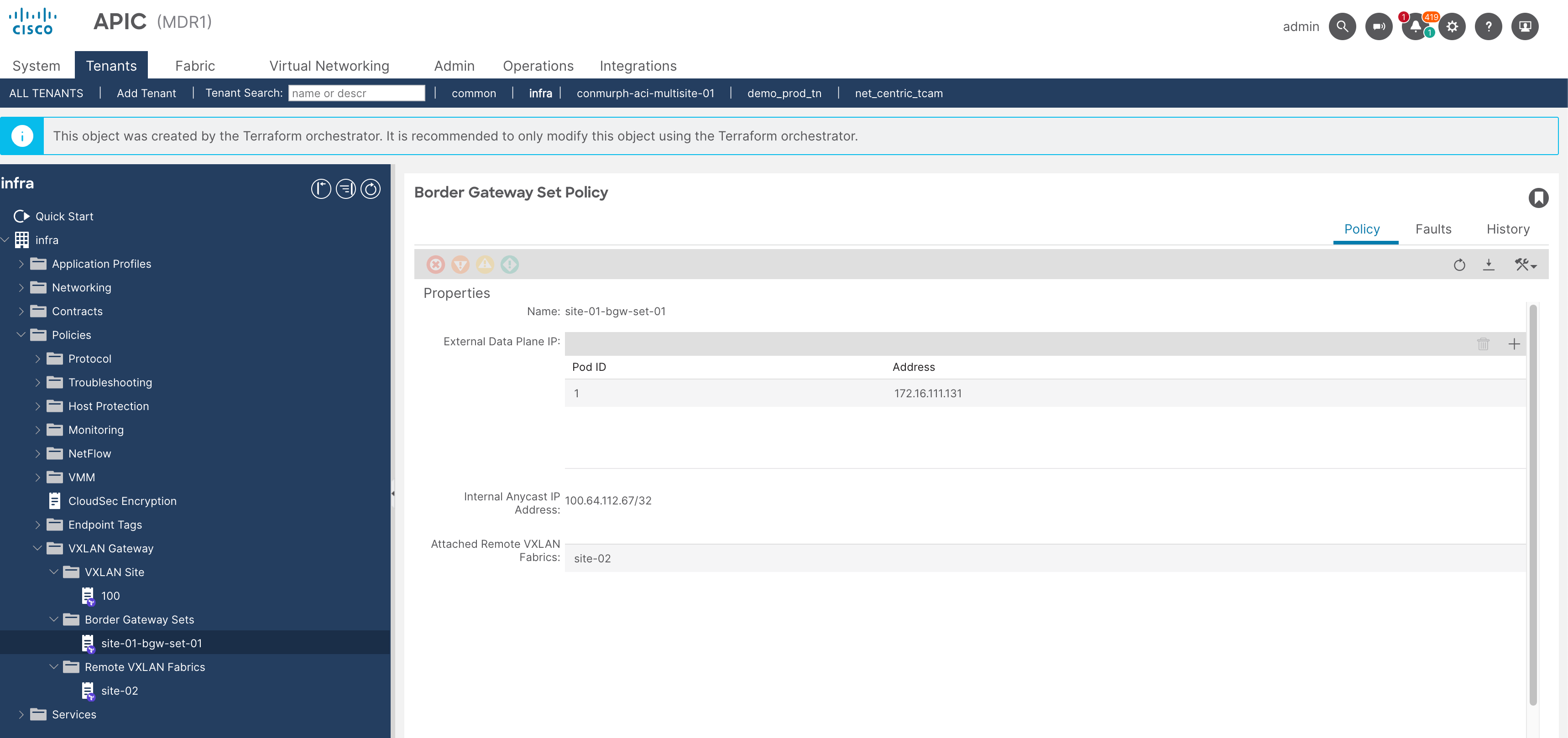
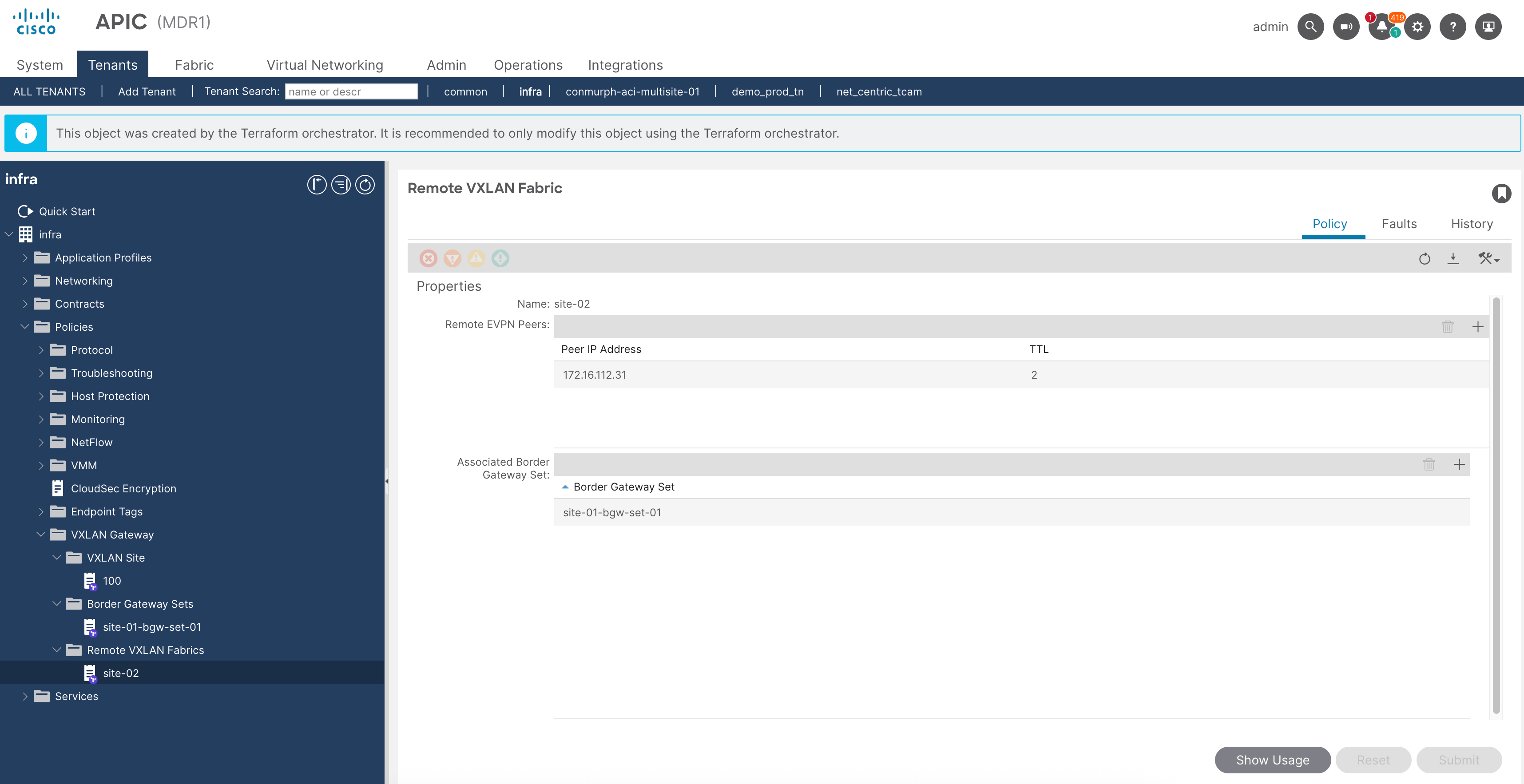
Verify the infra tenant config at both sites.

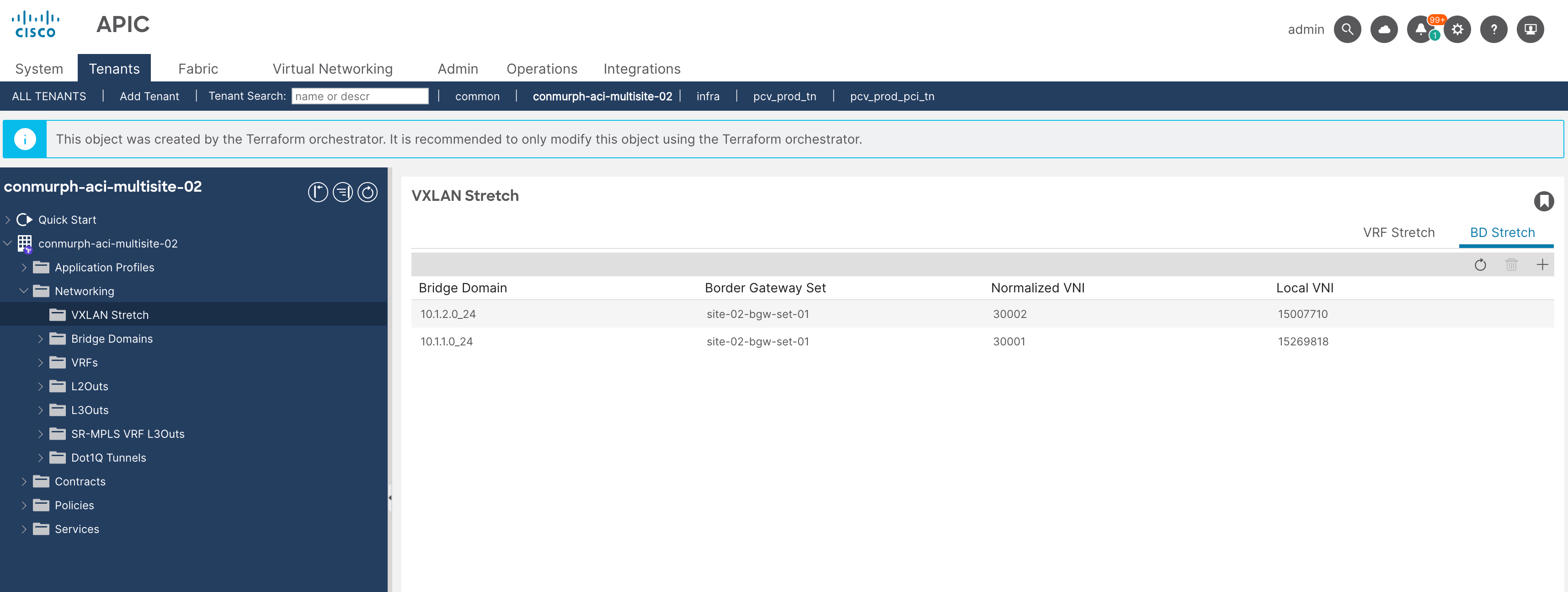
Verify the VRF/BDs under the VXLAN Stretched Objects
If you need to check the VXLAN EVPN sessions you can run the following commands.
show bgp l2vpn evpn summ vrf overlay-1show bgp l2vpn evpn vrf overlay-1show bgp l2vpn evpn 10.1.1.11 vrf overlay-1show ip interface